Boiler Lagging Tests
Chuck Hackett, 12/1/01
I ran these tests to determine the effects of adding a jacket and lagging
(insulation) to my locomotive. Most people add a jacket to their
locomotive. One reason is that the prototypes had them, another is that it
adds a finished look. Most people add lagging also since they believe that
it conserves heat (fuel) and thus a better steaming locomotive. Some do
not add lagging as they believe that the benefit isn't worth the trouble.
So ...
- What is the reduction in heat loss realized by adding a jacket to the
boiler with an air gap between the boiler and the jacket?
- What is the reduction in heat loss realized by adding lagging under the
jacket?
To answer these questions I ran some tests while in the process of replacing
the boiler on my locomotive (see UP 844
Catches The Flu(e) to see why it had to be replaced).
The Test Setup
The boiler was off the locomotive frame and setup on one of my engine
stands. This makes access to the burner, jacket and lagging a lot easier.
All water openings were plugged except that the two safety valves were
installed and the feed to the cab turret was fitted with a 90 degree turn valve
and piping to lead overflow away from the boiler/jacket, etc.
The smokebox was installed including the smokestack assembly and the smokebox
door. The opening in the bottom of the smokebox that accepts the exhaust
nozzle was covered with duct tape. This left a normal gas path and
smokebox configuration except that there were many 5-40 size bolt holes left
open (smokebox door bolts, etc.). I didn't feel that these would have a
large effect on the outcome.
To provide draft I fitted a U-shaped piece of copper tube into the stack fed
from my shop air compressor via an adjustable regulator.
I fitted a type "J" thermocouple probe in the crown sheet
inspection port (1/2" NPT) in the backhead. The tip of the the probe
was just above and to the rear of the crown sheet. This is probably the
hottest part of the boiler. I would have liked to have fitted another
thermocouple to measure the water temperature at the front flue sheet also but I
didn't have time to set that up. My thermocouple meter is calibrated in
degrees C and only shows whole digits (i.e.: no digits after the decimal
point). If the reading was flipping back and forth I read this as
?.5. So the data has errors due to the lack of resolution of the meter.
Test 1
For the first test there was no jacket or lagging installed on the boiler.
Test Sequence:
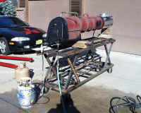 |
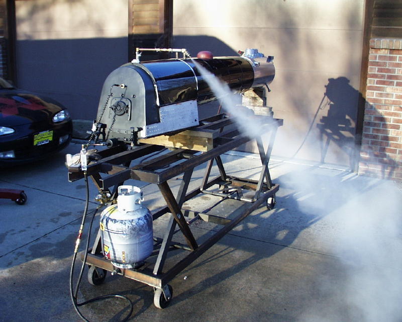
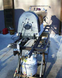
Here you can see the general test setup with the thermocouple probe
fitted in the backhead as well as a flow meter (Plexiglas device) on
the propane line. The boiler is heating up and water is coming
out of the turret pipe. |
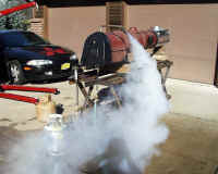 |
This is just before I turned off the burner, plugged the stack and
moved the boiler into the shop.
This is the first steam from my new
boiler! |
Test Results:
| Time |
Time From Start |
Boiler
Temp (C) |
Boiler Temp (F) |
Shop
Temp (F) |
Delta T |
| 12:20:00 |
0:00:00 |
100.0 |
212.0 |
61.0 |
151.0 |
| 12:25:00 |
0:05:00 |
99.0 |
210.2 |
62.0 |
148.2 |
| 12:30:00 |
0:10:00 |
98.0 |
208.4 |
63.0 |
145.4 |
| 12:35:00 |
0:15:00 |
97.0 |
206.6 |
64.0 |
142.6 |
| 12:40:00 |
0:20:00 |
95.0 |
203.0 |
64.0 |
139.0 |
| 12:45:00 |
0:25:00 |
94.0 |
201.2 |
64.0 |
137.2 |
| 12:50:00 |
0:30:00 |
92.0 |
197.6 |
64.0 |
133.6 |
| 12:55:00 |
0:35:00 |
91.0 |
195.8 |
64.5 |
131.3 |
| 13:00:00 |
0:40:00 |
89.0 |
192.2 |
65.0 |
127.2 |
| 13:05:00 |
0:45:00 |
88.0 |
190.4 |
65.5 |
124.9 |
| 13:10:00 |
0:50:00 |
86.5 |
187.7 |
65.5 |
122.2 |
| 13:22:00 |
1:02:00 |
82.0 |
179.6 |
66.0 |
113.6 |
| 13:25:00 |
1:05:00 |
81.0 |
177.8 |
66.1 |
111.7 |
| 13:30:00 |
1:10:00 |
79.5 |
175.1 |
66.0 |
109.1 |
| 13:35:00 |
1:15:00 |
78.0 |
172.4 |
66.0 |
106.4 |
| 13:40:00 |
1:20:00 |
77.0 |
170.6 |
66.0 |
104.6 |
| 13:53:00 |
1:33:00 |
73.5 |
164.3 |
66.0 |
98.3 |
| 14:07:00 |
1:47:00 |
70.0 |
158.0 |
66.0 |
92.0 |
| 14:32:00 |
2:12:00 |
65.0 |
149.0 |
65.5 |
83.5 |
Test 2
For the second test I installed the jacketing but no lagging. This
jacketing covers the entire boiler except for the backhead and about the last 3
inches of the rear outer wrapper. This is where the cab will be installed
later.
The jacket is held off the boiler by steel rings at about 8 inch
intervals. The air gap ranges from about .25" at the smokebox end to
about .625" at the cab end. The lower portion of the firebox (except
for the rear, under the cab) is also covered by riveted (to simulate scale
staybolts) false firebox sides. There is an (essentially trapped) air gap
of .25" on the lower firebox.
Test Sequence:
The test procedure for this test was identical to test 1.
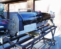 |
Test 2 warming up. Entire boiler is covered by jacketing
except for the area which will be covered by the cab. |
 |
A better view of the thermocouple probe installation and the flow
meter. The flow meter is calibrated 0 to 10 GPH of water but it
worked fine for setting the burner flow the same in both tests.
Sometime in the future I'll calibrate it in CFM of propane. |
 |
Test 2, ready to roll it into the shop and start recording numbers |
Test Results:
| Time |
Time From Start |
Boiler
Temp (C) |
Boiler Temp (F) |
Shop
Temp (F) |
Delta T |
| 16:06:00 |
0:00:00 |
100.0 |
212.0 |
64.5 |
147.5 |
| 16:10:00 |
0:04:00 |
99.5 |
211.1 |
64.5 |
146.6 |
| 16:16:00 |
0:10:00 |
99.0 |
210.2 |
65.0 |
145.2 |
| 16:23:00 |
0:17:00 |
97.5 |
207.5 |
65.1 |
142.4 |
| 16:27:00 |
0:21:00 |
97.0 |
206.6 |
65.0 |
141.6 |
| 16:35:00 |
0:29:00 |
95.5 |
203.9 |
65.5 |
138.4 |
| 16:38:30 |
0:32:30 |
95.0 |
203.0 |
65.8 |
137.2 |
| 16:45:00 |
0:39:00 |
93.5 |
200.3 |
65.8 |
134.5 |
| 16:54:00 |
0:48:00 |
92.0 |
197.6 |
66.0 |
131.6 |
| 17:01:00 |
0:55:00 |
91.0 |
195.8 |
66.0 |
129.8 |
| 17:06:00 |
1:00:00 |
90.0 |
194.0 |
66.0 |
128.0 |
| 17:10:00 |
1:04:00 |
89.0 |
192.2 |
66.0 |
126.2 |
| 17:21:00 |
1:15:00 |
87.0 |
188.6 |
66.0 |
122.6 |
| 17:25:00 |
1:19:00 |
86.5 |
187.7 |
66.0 |
121.7 |
| 17:45:00 |
1:39:00 |
83.0 |
181.4 |
65.5 |
115.9 |
| 18:01:30 |
1:55:30 |
79.0 |
174.2 |
65.0 |
109.2 |
| 18:17:45 |
2:11:45 |
76.0 |
168.8 |
64.5 |
104.3 |
Note the shop temperature rise in both tests. The furnace never
came on, the boiler was heating my shop which is an insulated 2 car
garage!
Test 3
For the third test I installed the lagging under the jacketing. The
lagging consists of a powdered form of asbestos that turns to a thick paste when
water is added and hardens to something like a grainy, fibrous Plaster of Paris.
It is not dangerous when in its paste form and is entirely enclosed by the
jacket after it has been installed. Again, the jacketing (and lagging)
covers the entire boiler except for the backhead and about the last 3 inches of
the rear outer wrapper.
The lagging varies in thickness from about .25" at the smokebox end to
about .625" at the cab end of the boiler. The lower outside portion
of the firebox is also covered to a thickness of approximately .25".
Test Sequence:
The test procedure for this test was identical to tests 1 and 2.
To see how the lagging was installed you can click here.
Test Results:
| Time |
Time From Start |
Boiler
Temp (C) |
Boiler Temp (F) |
Shop
Temp (F) |
Delta T |
| 21:20:00 |
0:00:00 |
100 |
212.0 |
63 |
149.0 |
| 21:25:00 |
0:05:00 |
99 |
210.2 |
63.5 |
146.7 |
| 21:30:00 |
0:10:00 |
98 |
208.4 |
63.7 |
144.7 |
| 21:35:00 |
0:15:00 |
97 |
206.6 |
63.9 |
142.7 |
| 21:40:00 |
0:20:00 |
97 |
206.6 |
63.9 |
142.7 |
| 21:45:00 |
0:25:00 |
96 |
204.8 |
64 |
140.8 |
| 21:50:00 |
0:30:00 |
95 |
203.0 |
64 |
139.0 |
| 22:00:00 |
0:40:00 |
93 |
199.4 |
64 |
135.4 |
| 22:11:00 |
0:51:00 |
91 |
195.8 |
64 |
131.8 |
| 22:29:30 |
1:09:30 |
88 |
190.4 |
64.5 |
125.9 |
| 22:51:00 |
1:31:00 |
84 |
183.2 |
65 |
118.2 |
| 23:11:00 |
1:51:00 |
81 |
177.8 |
65 |
112.8 |
| 23:34:30 |
2:14:30 |
78 |
172.4 |
65 |
107.4 |
Comparing Tests 1, 2 and 3
I have combined the graphs from the three tests and shifted them in the
time domain to bring the 100 degree centigrade boiler temperature point to
time 0.
It's obvious that adding the jacket (forming a trapped air gap) made a
difference. It's also very obvious that adding the lagging material
added no benefit in reducing heat loss. It was no better than a trapped
air gap.
Two additional data items needed for this calculation are the fact that
there is approximately 500 pounds of steel (and minor amount of copper for the
flues) in the boiler and for each test there was 15.4 gallons of water in the
boiler.
Conclusion
It is of benefit to add at least a jacket around the boiler to form a
trapped air gap.
Even though the lagging is not providing me any benefit in thermal terms it
does provide a hard foundation for the jacket and minimizes chances of
inadvertently denting the jacket.
Next Steps
I still need to calculate the R-value of the jacket/air gap combination and the expected
fuel savings.
I'll post the results here when I get them done. Email
me if you would like to be notified when the page is updated.
This Page has been viewed
 times since 12/01/01
|