![]()
![]()
![]()
![]()
![]()
![]()
![]()
![]()
|
|
|
|
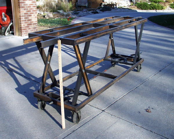
My Engine Stand(you may click on photos for a larger version)
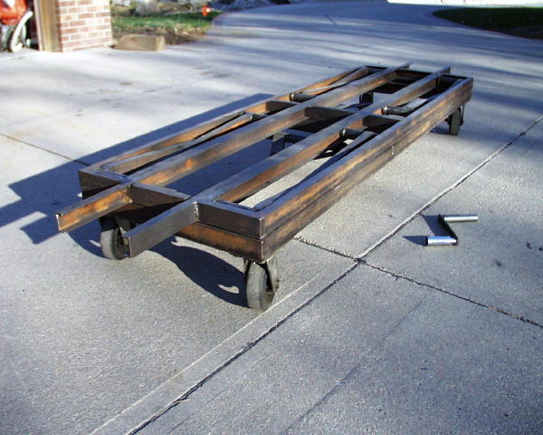
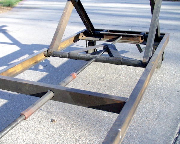
I needed a stand to work on my UP Northern (4-8-4) but I couldn't decide what height to make it so I decided to make it's height adjustable. My goal was to construct it in such a manner that I could collapse it to as small a package as possible to allow me to transport it to shows, etc. Since my engine weighs approximately 1,600 pounds the stand obviously had to be strong. The "rail" area had to be about 8' long and I decided that a single scissors lift design would not be stable enough so I opted for a double scissors design. This meant that I had to find a way to operate the scissors in unison so that the rail remained level. I accomplished this by using two threaded rods, one right-hand thread and the other left-hand thread. These two rods were coupled end-to-end and can be seen in the center of the lower level of the stand.
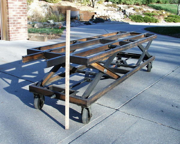
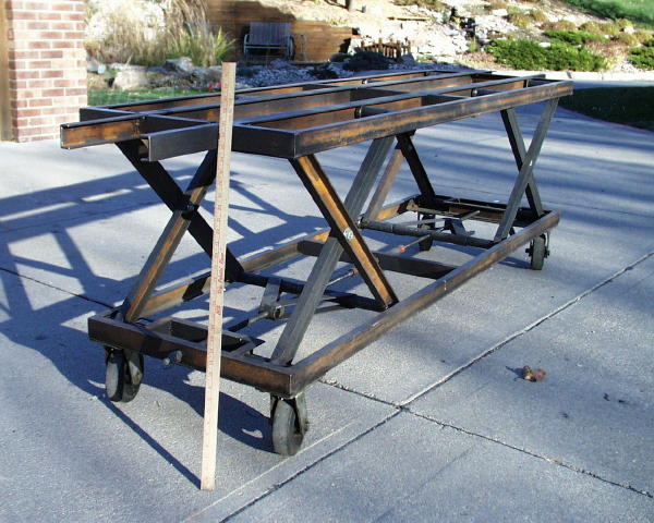
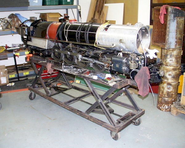
Final Result:
Note 1: The lower operating limit is determined by the load placed on the stand. As the "X"'s become lower the stress on the lead screw grows to infinity according to the tangent of the angle of the X arm with the horizontal. 1,600 pounds of load could easily strip the lead screw or break welds, etc. I never operate the stand below about 24" height when the engine is loaded. The following table and diagram show the tension in the leadscrew as a function of stand height (the arms of the X are 29" long) with a load of 1,600 pounds (my locomotive). "Angle" refers to the angle of the X arm to the horizontal, "spread" is the width of the bottom of the X between the fixed and movable pivot. This does not include friction losses. (Click on graph for larger image)
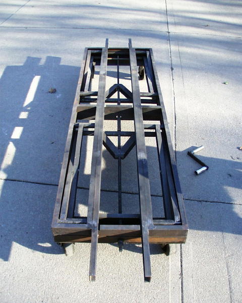
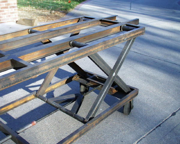
I'm afraid that the threaded rod would not last too long if I attempted to operate the stand below about 20 inches with my locomotive on it. Note 2: The upper operating limit is determined by a limit of stability. If the "X"'s were allowed to become very tall and thin and the table would become unstable in the lengthwise direction. Photo S4 below shows that the member that holds the nut on the lead screw is arranged such that they limit how thin the "X"'s are allowed to become. The top level (R2) was constructed by first welding up the center rail from two channels face-to-face separated by spacers cut to the proper gauge. Then I fabricated two rectangles that the X's ride in and welded these to either side of the central rail section. You need to be sure that the welds holding the rectangles to the central section are sturdy because this joint will be under a lot of stress. I ground a 45 and welded the entire length of the underside of the center joint (under tension) and tack welded the top side of the joint (under compression). In R1 and R2 above you can see a crank handle. I made this from some scrap and a deep well socket that fits the drive nuts on the ends of the lead screw. The lift can be disassembled by just removing the lead screw and the 4 bolts at the pivots of the "X"'s. The only negative is that the stand is very heavy (I usually end up overbuild things). I designed the lift so that when it is raised it's open on the bottom. If I need to work on the under side of the engine I can lay a piece of plywood on the lower level. I can also place the tender on the lower level to save floor space during winter storage.
Construction Details:
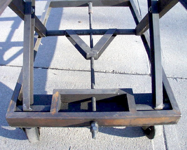
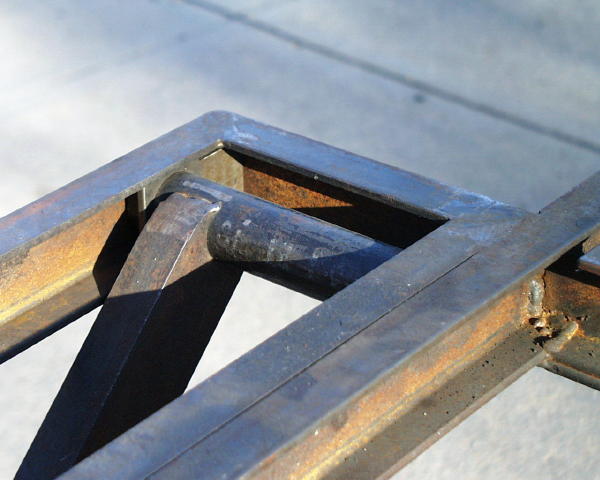
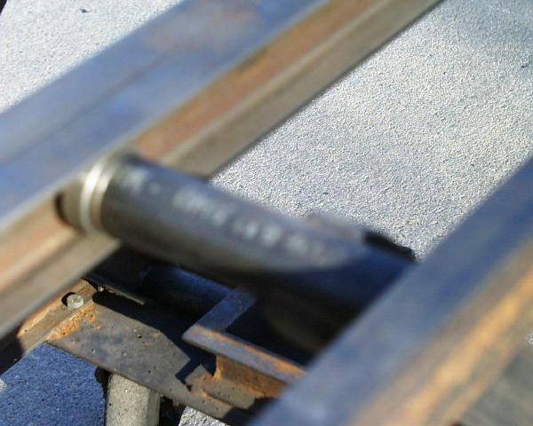
Most of the lift was constructed from 1" x 2" steel channel and two sizes of black pipe (one fits inside the other). (S1) The center pivot of the X's is constructed with a bronze bushing in a reamed hole and a bolt with two washers to fasten the assembly together. (S2) Note that the pipes at the ends of the X arms are all the same length. The triangle piece in the center is fabricated from pipe the same size as that used on the ends of the X arms and .125" x 2" flat strip. The nut is at the apex of the triangle. There is a section of the smaller pipe that goes through the to lower ends of the X's and the wide end of the triangle. (S3) One of the reasons that I used left and right-hand thread is that this allows the two rods to be connected end-to-end. This allows the rods to easily carry the tension load caused by the X's. This load increases to infinity (tangent of angle of arm to the horizontal) as you lower the lift. Someone suggested using only right-hand thread and gearing the rods in the center. If you did this you would have to arrange some method to take this load through thrust bearings with jamb nuts. Be sure the rods are under tension, not compression. Under compression they would be in danger of buckling. Also check to see if the gears will interfere with your ability to use the lower level for winter storage if desired. I purchased my rod and nuts from a local company that makes them for MSC. You can check locally or purchase direct from MSC (6 ft max, I think). In my first lift I used 60 degree thread but switched to acme threaded rod for the second one. Acme thread is much stronger and requires less torque to achieve a given force.
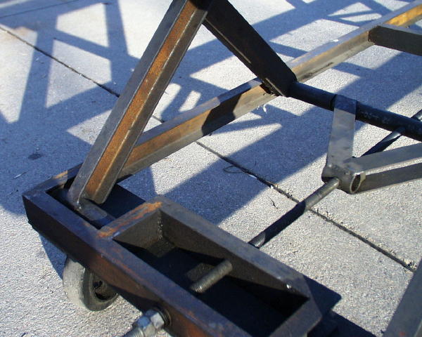
Each of the fixed pivots (D1 & D2) are constructed with concentric iron pipe. One is welded to the end of the X arm and bears against the plate shown. The other pipe fits inside the first pipe and extends from one channel wall to the other. Unseen behind the plates is a stand-off ring on the second pipe which keeps the plate about 3/8" from the channel wall. This keeps the plate away from the welds in the corner and prevents the inner pipe from twisting out of the plate causing disaster. To facilitate disassembly the fixed pivots are not welded in place. In D1 and D2 you can see 1/8" thick plate through which the inner pipe forming the pivot passes. These are forced into the corners by the normal forces involved in lifting. The lower fixed pivots are constructed in the same manner. The moving pivots are basically the same as the fixed pivots except that the 1/8" plate has been replaced by ball bearings that fit in the "C" of the channel. The bearings are each on a turned shaft that fits about .75" into the pipe and flush with the outside face of the bearing. there is also a .25" hole in the end of the stub shaft that accepts nylon "button" I turned to ride on the channel wall and hold the bearing on the stub axle. One question I've been asked is why I used the back-to-back channels in the center of the upper level rather than letting the bearings ride in the front face of a single channel and use the back side to run on. As I recall I had the following thoughts:
There is another aspect of the construction that is not visible in the photos: there is a piece of 1/8" x 1" strap steel welded to the underside of ends of the upper level. It's purpose was to resist the tendency for the welds at the bottom of the center members to fail due to the tension load on the bottom welds (the load is in the center but they are supported at their outer ends). This is probably overkill but we're talking about a stand for a 1,600 pound locomotive :-) This reinforcement might not be needed but if you have any doubts about your welding/engineering abilities it's cheap insurance and a lot easier than repairing an arm or the locomotive :-)
Still To Do:I intend to make two "trays" that will sit on the top level next to the "rail" for small parts, tools, etc. I also want to add rollers to facilitate test running the engine.
Things I would do differently:Hydraulics: At the time I built the lift I wanted to use hydraulics but I couldn't figure out how to synchronize the two scissors without resorting to the complexity of flow dividers, etc. I think I have a solution to this and I'll probably convert it to hydraulics in the future. As I get older it will be harder and harder to bend down to crank it up and down :-) Wheels: The wheels on the stand are heavy duty wheels with a hard rubber tire. When the stand has my locomotive on it the rubber squashes causing too much rolling resistance. I wish I had used steel wheels.
Other People's Designs and Adaptations:
Legal Notice: Never place parts of your body in or under the stand as there is a danger of collapse. I am not a licensed engineer or welder. Consider this information as a suggested design only and consult an appropriate engineer and welder if you do not have the required skills. |