![]()
![]()
![]()
![]()
![]()
![]()
![]()
![]()
|
|
|
|
Automatic Air Brakes for riding scale rolling stock
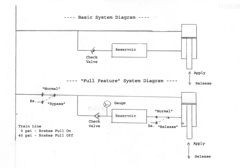
The system relies on the fact that the check valve to the car brake reservoir has a 'cracking pressure' (i.e.: pressure loss) of about 2 psi and the 'rod end' of the cylinder has a smaller effective area than the piston end. Due to the check valve loss the car brake reservoir pressure will be approximately 2 psi lower than the 'full release' train line pressure. The lower car brake reservoir pressure and the smaller effective area of the cylinder rod end allow the piston to be forced into release (as opposed to just going slack) when the train line is at the 'full release' setting (40 psi in my case) so no 'hold off' springs are required to keep the brake shoes from dragging. In the 'Full Feature' system the 'Normal/Bypass' switch allows the car to be cut out of the train line if there is a malfunction on the car (leak, etc.). The 'Normal/Release' switch is used to force the brakes off in the absence of train line pressure (e.g.: the car is disconnected from the train) allowing the car to be moved. In practice, the car brake reservoirs on my cars (2" PVC pipe about 30" long) allows the brakes to be released and applied many times before it is exhausted.
Added 2010-08-09: There has been discussion of a similar system that has an added pressure regulator between the reservoir. I will add more on this later but for now here is a PDF that shown some of the pressure differences:
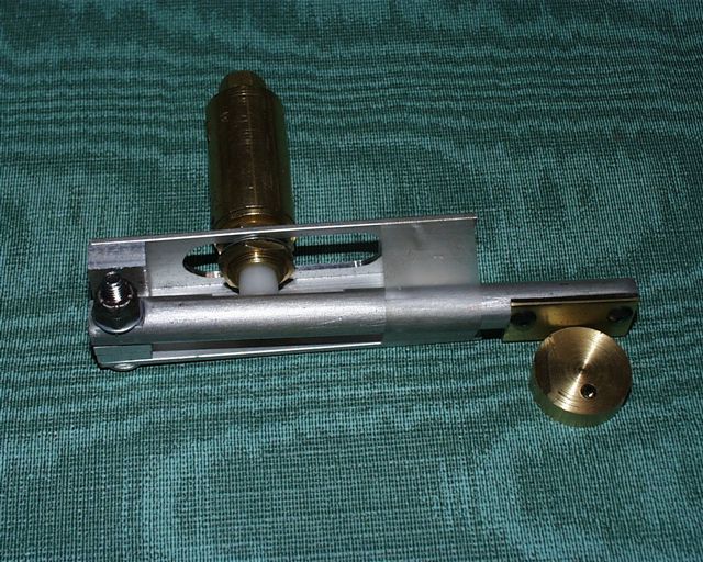
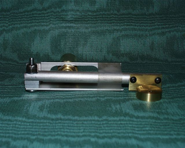
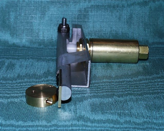
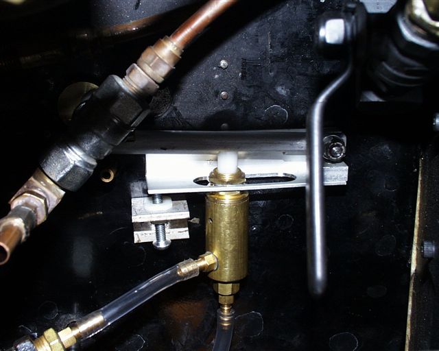
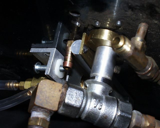
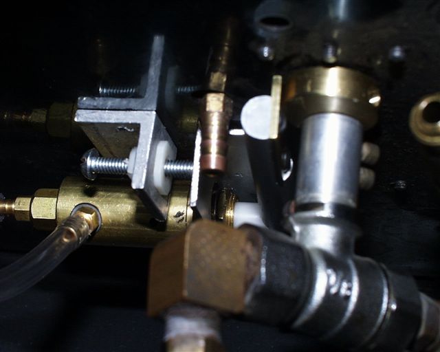
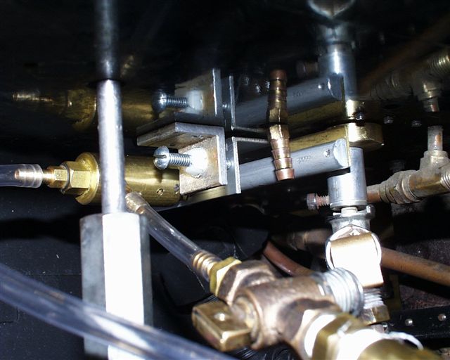
Brake StandSeveral people have asked me recently about how I setup the brake stand to control the train line pressure so I have put together a quick piece here. It's rough, but should give you the idea. Let me know if more information is needed. The brake stand approach I used is similar to many in that it makes use of a Clippard MAR-1 pushbutton type regulator (as I recall 0.250" of travel = 0 to 120 psi or so). The regulator is actuated by a brake stand in the cab that has a shaft extending below the cab floor to a brass eccentric (disk with an off-center hole for the shaft). This is fairly normal practice but most people have the plunger of the MAR-1 touching the outside surface of the eccentric (or a cam shape of some sort). As you rotate the eccentric through a 90-degree arc it pushes or releases the plunger thus altering the train line pressure. This works fine, but, if you want to change the max train line pressure, you must machine a new eccentric to change the plunger travel. When I was installing my brake system I didn’t know what train line pressure I wanted to run and I didn’t want to have to machine a new eccentric each time I wanted to change the train line pressure. The arrangement described below allows me a wide adjustment range in train line pressure without having to machine anything. DescriptionIn my approach the eccentric does not press directly on the plunger of the regulator. My eccentric touches the end of a lever that is about 4 ” long. The eccentric is machined so that it creates slightly more than 0.250" of travel in the end of the lever when the eccentric is rotated through 90 degrees. The opposite end of the lever is fixed by a pivot point. The MAR-1 is mounted in a bracket with a slot machined into it (the bracket is roughly parallel with the lever). This slot allows the MAR-1 to be positioned anywhere along the lever with the MAR-1’s plunger pressing on the lever (opposite side from the side the eccentric pushes on). The bolt (pivot) that holds the fixed end of the lever comes down through the cab floor, through the end of the bracket the MAR-1 is mounted on and finally through the end of the lever to form its pivot point. The position of the free end of the bracket can be adjusted closer and further away from the lever. This rotates bracket around the same pivot point as the lever, moving the whole assembly closer to, or further from the eccentric. (photos below) To adjust the pressure:First you move the MAR-1 in the slot. If you want a higher pressure, you move it towards the eccentric end of the bracket, for lower pressure, you move it away from the eccentric. In actuality this is adjusting the “range” or total movement of MAR-1 plunger for a 90-degree rotation of the brake stand lever. After you move the MAR-1 you adjust the free end of the bracket closer to, or further from, the eccentric to set the “zero” point – i.e.: The point where the lever is just touching the MAR-1 plunger when in “full apply” position (causing the MAR-1 to drop the train line to 0 psi).. These adjustments interact so you’ll have to repeat the process until you get the train line pressure you want at “full release” and 0 psi at “full apply”. Keep in mind that the exhaust hole in the MAR-1 is not big (about 0.0625"), so, with a significant train line length (mine is about 120 feet) there will be a delay in braking action after moving the brake stand lever – even in “big hole” mode. So, just like on the full size stuff, you have to anticipate.
OperationI really like the automatic airbrakes. With the regulator you can smoothly control the brakes from full off to full on and anywhere in between with the comfort knowing that, if the train parts, everything comes to a stop without you having to react - and faster because the air is escaping through the (relatively) large 'hole' created by the parted train line. One thing to be aware of is that (unlike "straight air" brakes) the train line is under pressure most of the time. You have to be sure that ALL connections are tight and leak free. If not, your compressor will run excessively, and in the worst case, it will run so much that it drains the battery. When that happens, the train will get “heavier and heavier” as the train line pressure drops and the brakes start dragging (ask me how I know ...). At that point you have to manually release the brakes on each car and limp back to the yard without effective braking. I have considered building a voltage activated cutoff that would kill the compressor if the battery voltage falls abnormally low (I think these devices are available for RV batteries?). When it cuts the power to the compressor the train will start to drag as the train line pressure drops. When you investigate the cause of the drag you will hopefully find the leak and isolate the offending car. You can then activate a manual bypass switch allowing the compressor to use the last of the battery to keep the brakes functional enough to make it back to the yard and recharge the battery.
PlumbingJust about any plumbing that is leak free will work. I find that the "push on" type fittings used for industrial pnumatics (internal O-ring with an external ring you push to release) are easy to install and work well if you use the correct plastic tubing. Do Not use common clear plastic "aquarium" tubing! If you do, you will be fighting leaks forever (again, ask me how I know ...). This is because, over time, the O-ring deforms the tubing causing the O-ring to loose its grip on the tubing. You must use the harder plastic tubing that they sell for use with these fittings. If you use small diameter plastic tubing on barb fittings (like the small ones for use with Clippard valves, etc.) it's a good idea to use the locking rings that they provide.
ExtrasAt the start of a run day it's a good idea to test the brake system for leaks. You can't do this with the brake stand regulator in the circuit because it will attemp to compensate for leaks by adding air. My procedure is:
I hope this all proves helpful. Some photos to clarify things
|