The project:
This page deals with some discussion we have been having on the LiveSteamers
email list about the best way to machine a set of 1.6" scale Cross-Compound pump
castings I have.
 |
|
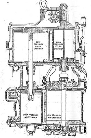
A prototype Westinghouse Cross Compound Air Pump |
I have been thinking about how I will approach machining the castings I have
for a 1.5" scale cross-compound air pump.
The main challenge is to machine the three main castings such that the upper
and lower cylinder bores, as well as the corresponding piston rod glands are all
concentric and parallel within a high tolerance.
 |
|
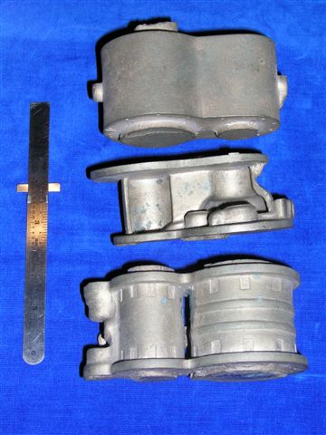
Photo 1: The three main castings (Castings from Ulin
Locomotive Works) |
 |
|
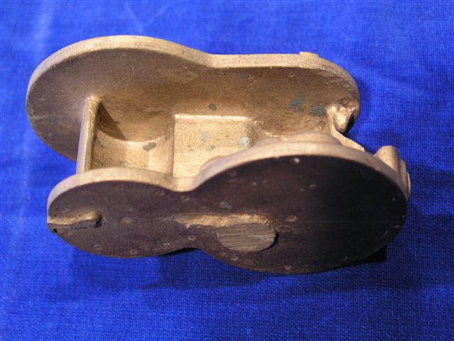
Photo 2: Close-up of the spacer casting |
On a simplex pump (only one set of cylinders) this problem is somewhat easier
because you can machine close-fitting bosses on the face of the spacer casting
to register the cylinder accurately to the piston rod gland. However, in
the cross-compound, not only would the bosses have to be EXACTLY the same
distance apart but they would both have to be exactly concentric to their
respective piston rod glands. I don't see a way to accomplish this on
opposite faces of the spacer casting to a sub-0.001 tolerance.
There is also not a lot of "meat" on the face of the spacer casting to
machine much of a boss and still have sufficient thickness remaining.
My current thoughts are to proceed as follows:
| 1 |
Mill (fly cut) the bottom (side that mates to the spacer casting) of the
steam cylinders (upper casting) and bore the larger (low pressure) steam
cylinder in the same milling setup. This guarantees that the cylinder
is 90 degrees to the lower face of the casting |
| 2 |
Flip over the upper casting and fly cut the upper surface parallel with
the lower surface |
| 3 |
Fly cut the top (side that mates to the spacer casting) of the air
cylinders (lower casting) and bore the larger (low pressure) air cylinder in
the same milling setup. This guarantees that the cylinder is 90
degrees to the upper face of the casting |
| 4 |
Flip over the lower casting and fly cut the lower surface parallel with
the upper surface |
| 5 |
Fly cut the upper and lower surfaces of the spacer block (center
casting) flat and parallel |
| 6 |
Bolt the sections together, adding two locating pins between the spacer
block and each set of castings to be absolutely sure that they always go
together in the same relationship |
| 7 |
Mount a suitable piece of stock in the lathe and make an expanding
mandrel with a drawbar extending thru headstock. It must be a tight
fit to one of the larger bored cylinders. |
| 8 |
Without disturbing the mandrel, slide the large cylinder onto the
mandrel and tighten. The centerline of the mandrel is now parallel and
concentric with the axis of the large cylinder. |
| 9 |
Bore the opposite (smaller) cylinder using a very low RPM due to the
imbalance of the castings. |
| 10 |
Without disturbing the mandrel or the cylinder block and spacer mounted
on it, unbolt the outer cylinder casting from the spacer block |
| 11 |
Drill, bore and ream the rod hole thru the spacer section glands (again
at low RPM) |
| 12 |
The axis of the two cylinders and rod glands are now concentric to a
high degree of accuracy determined primarily by the fit of the mandrel in
the large cylinder and the accuracy of the lathe |
| 13 |
Repeat steps 7 thru 12 using the second large cylinder (this assumes
that the second large cylinder is a different size than the first. If
not, skip step 7) |
| 1 |
Mill (fly cut) both mating surfaces of the three castings flat and
parallel |
| 2 |
Bolt the sections together, adding two locating pins between the spacer
block and each set of castings to be absolutely sure that they always go
together in the same relationship |
| 3 |
Mount the assembled castings on the lathe faceplate centering it on one
of the cylinder bores. |
| 4 |
Bore the cylinder on the outer end (all turning operations are done
using a very low RPM due to the imbalance of the castings) |
| 5 |
Remove the outer cylinder |
| 6 |
Drill, bore and ream the rod hole thru the spacer section glands |
| 7 |
Remove the spacer casting |
| 8 |
Bore the cylinder on the inner end |
| 9 |
Repeat steps 2 thru 8 centering on the second cylinder set |
| 1 |
Mill (fly cut) both mating surfaces of the three castings flat and
parallel |
| 2 |
Rough drill the cylinder bores in the upper and lower castings |
| 3 |
Drill bolt holes and holes for locating dowels in the upper and lower
faces of the castings (see note below) |
| 4 |
Bolt the sections together, using two dowel pins between the spacer
block and each set of castings to be absolutely sure that they always go
together in the same relationship |
| 5 |
Mount the assembled castings vertically on the milling machine, locate
the spindle over the centerline of one of the cylinder bores and lock the
table. |
| 6 |
Bore the cylinder in the upper casting (see note below) |
| 7 |
Remove the upper cylinder casting keeping the table locked |
| 8 |
Drill, bore and ream the rod hole thru the spacer section glands |
| 9 |
Remove the spacer casting keeping the table locked |
| 10 |
Bore the cylinder on the lower casting |
| 11 |
Reassemble the castings and repeat steps 4 thru 10 centering on the second cylinder set |